Camshaft Installation
SAFETY FIRST: Protective gloves and eyewear are recommended at this point.


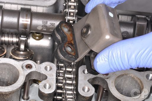
Insert the cam chain guide into the engine.


Turn the crankshaft clockwise with a 19 mm socket until the T mark on signal generator rotor lines up with the pickup coil as shown. Keep the cam chain taut while aligning the T mark.


The exhaust camshaft goes in the front and the intake camshaft goes in the rear of the cylinder head. Coat the camshaft journals thoroughly with Suzuki moly paste.
Suzuki Moly Paste: 99000-25140

 Look over the timing information first to line up your camshafts correctly. Install the camshafts into place and engage the cam chain to the sprockets.
Timing
| Cam chain pin (at arrow "3") | 21st pin (600, 1988-1995) (750) | ||
| Cam chain pin (at arrow "3") | 24th pin (600, 1996-1997) |
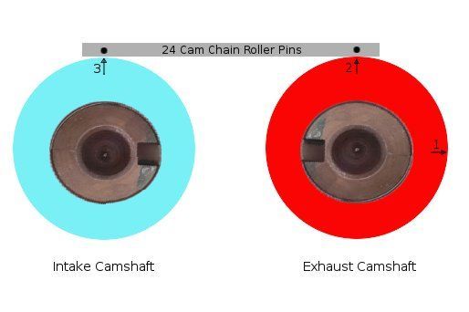
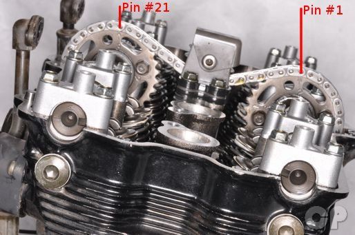
The camshaft sprockets are marked with numbers and arrows. The arrow next to #1 on the exhaust sprocket should be level with the cylinder head cover mating surface and facing forward. The exhaust camshaft sprocket #2 should be facing straight up. Starting with the roller pin directly above the exhaust #2 arrow count over 21 or 24 pins as indicated by model. Position the intake camshaft so that its #3 arrow is directly under the 21st or 24th pin as indicated by model.


Install the dowel pins and camshaft journal holders.


Make sure to install the journal holders to the correct location. See the photo below for more information.
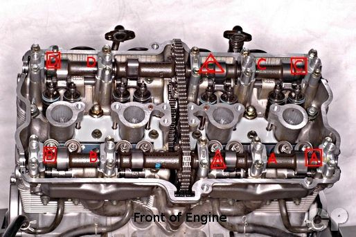
Install the camshaft journal holders as indicated.


Tighten the camshaft journal holder bolts to specification with a 10 mm socket.
(Camshaft Journal Holder Bolt Torque: 10 N-m or 7 lb-ft)


Install the cam chain idler as shown. Tighten the four mounting bolts to specification with a 10 mm socket.
(Cam Chain Idler Bolt Torque: 8 - 12 N-m or 6 - 8.5 lb-ft)


Install the cam chain guide. The arrow on the guide should face towards the front of the engine.
(Cam Chain Guide Bolt Torque: 8 - 12 N-m or 6 - 8.5 lb-ft)


Release the ratchet catch and push the tensioner rod all the way in.
Turn the crankshaft clockwise enough to remove slack in the cam chain between the timing sprocket on the crankshaft and the exhaust camshaft sprocket.


Install cam chain tensioner with a new gasket. Insert the mounting bolts and torque them to specification with a 5 mm Allen.
(Cam Chain Tensioner Mounting Bolt Torque: 7 N-m or 5.0 lb-ft)


Insert the spring into the tensioner. Install the tensioner cap bolt and a new sealing washer.
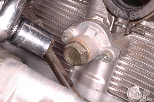
Tighten the cap bolt to specification with a 19 mm socket.
(Cam Chain Tensioner Cap Bolt Torque: 35 N-m or 25.5 lb-ft)
Turn the crankshaft clockwise with a 19 mm socket until the T mark on signal generator rotor lines up with the pickup coil as shown. Check your engine timing. Turn the motor over a full revolution make sure the timing is correct.
Pour around 50 ml of fresh engine oil into each of the 8 oil pockets in the cylinder head.
Check the valve clearance. See the Valve Clearance topic for more information.


Install the signal generator cover with a new gasket.


Insert the signal cover bolts. Install a new sealing washer with the forward most bolt. Tighten the bolts to specification with a 5 mm Allen.
(Signal Generator Cover Bolt Torque: 3 N-m or 2 lb-ft)
Install the cylinder head cover. See the Cylinder Head cover topic for more information.
Install the spark plugs. See the Spark Plugs topic for more information.
Copyright 2025 - Cyclepedia Press LLC

Note: If you are viewing this document offline be sure to visit the latest version online at http://www.cyclepedia.com before attempting any repairs. Updates are made without notice.